
Motorized Camera Slider
January 2020
Introduction
Motorized camera sliders are an essential piece of gear for timelapse photography, as they allow you to get much more dynamic and interesting shots than a stationary tripod. These sliders are very expensive, however. The cheapest ones start at $200, and for a decent travel length, expect to spend upwards of $400. In this project, I outfitted an ordinary $60 camera slider with an Arduino-controlled stepper motor. The final cost of the upgrade was just under $50.
The supplies I used for this project are
- Cheap non-motorized camera slider
- Arduino Micro
- Stepper motor
- 6mm timing belt and pulleys
- A4988 Stepper Motor Driver
- Momentary Push Button
- 10k Potentiometer
- SPDT Switch
- Mounting Hardware
As a starting point, I loosely based my design on Max Maker's similar project; however, instead of having four toggle switches for a speed control input, I opted for a single potentiometer and a single toggle "fast/slow" mode. Additionally, I wrote all the Arduino code from scratch to accommodate this operator interface.
Hardware
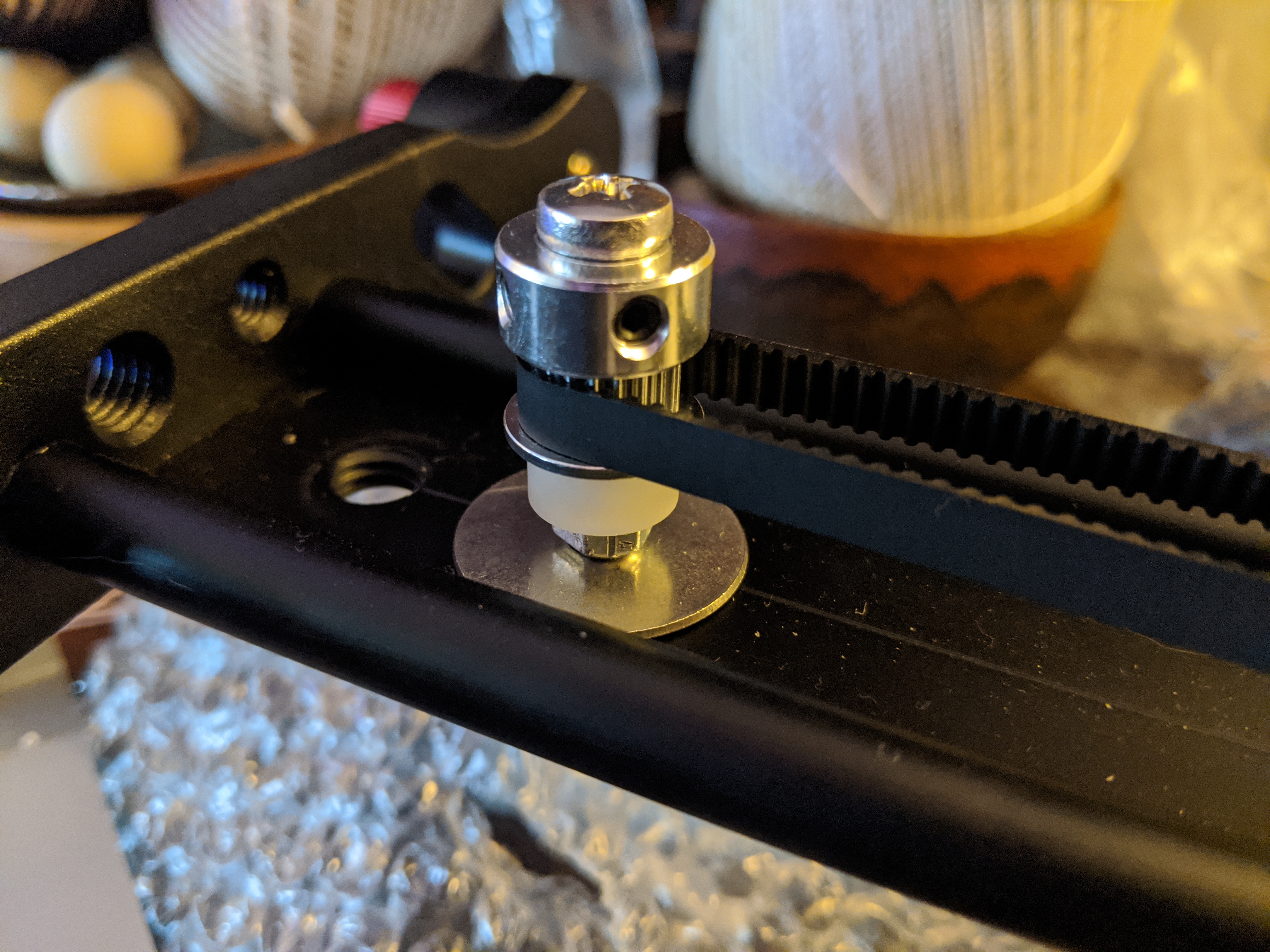
My main goal was to outfit the slider with the motor and pulley system while causing the lease amount of damage (cutting/drilling) to the slider as possible. I think I achieved this, since the entire thing came together by only drilling three holes. Starting with the pulley side, I used a pre-existing 1/4" tripod hole to mount the axle. The axle is a M5 screw to match the inner diameter of the pulley. It's fitted tightly to the slider using two lock-nuts and two washers, and then a nylon spacer allows the pulley to move freely around the axle.
Next, I mounted the stepper motor. I chose to only use two screws to mount the motor since using four would conflict with the side rails on the slider. The mounting holes did not line up well with the holes already in the slider, so I drilled three new holes that matched. The center hole must be slightly larger than the 5mm pulley axle so it can rotate freely, and the two side holes should be exactly 3mm for the mounting screws. The motor can then be mounted using M3 screws and the appropriate spacers both above and below the slider.
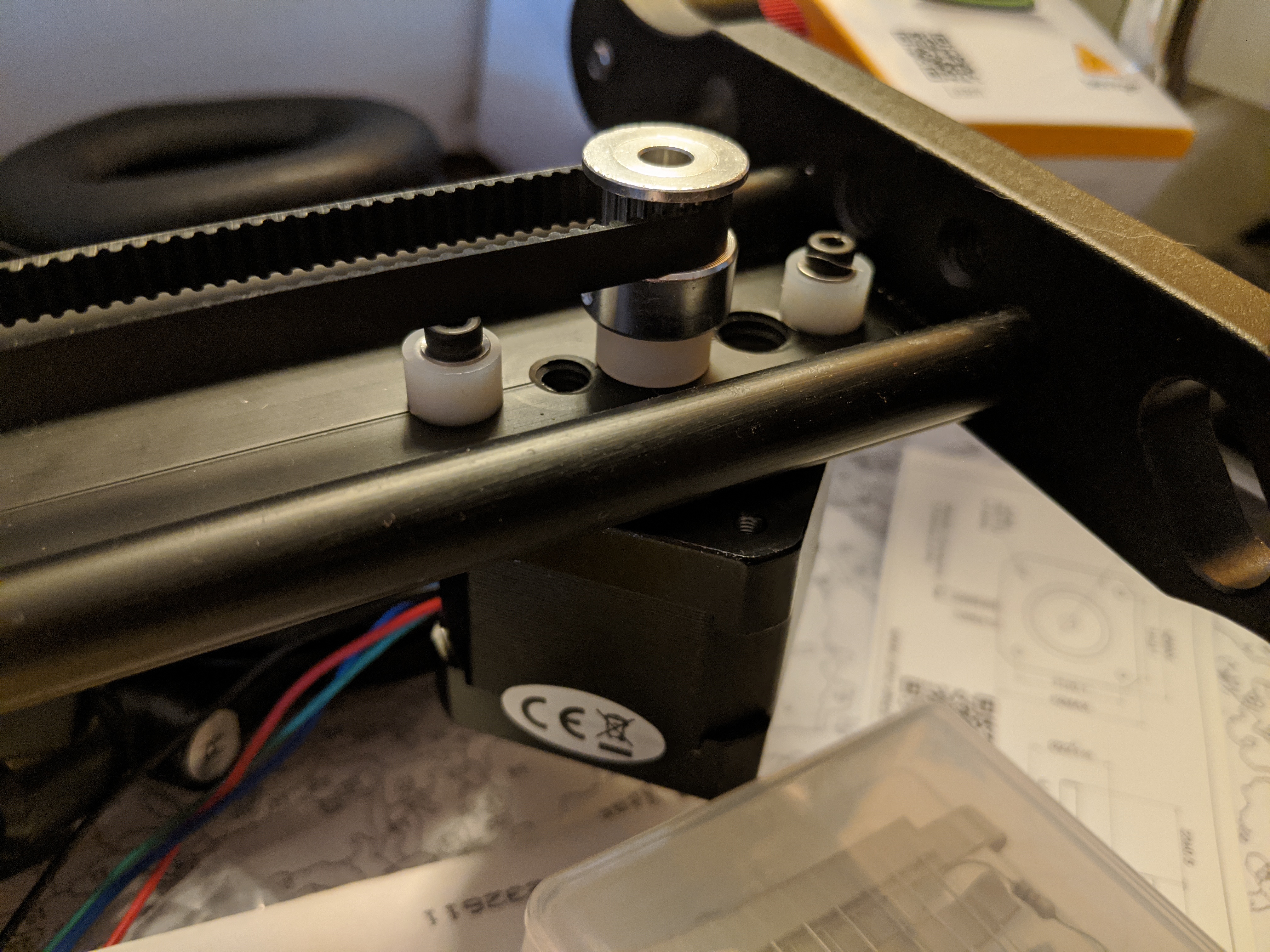
Lastly, we just need to attach both ends of the timing belt to the slider carriage. I again used an existing hole here, and attached the timing belt by threading it through the hole and zip-tying it to itself such that the teeth prevent slippage.
Electronics
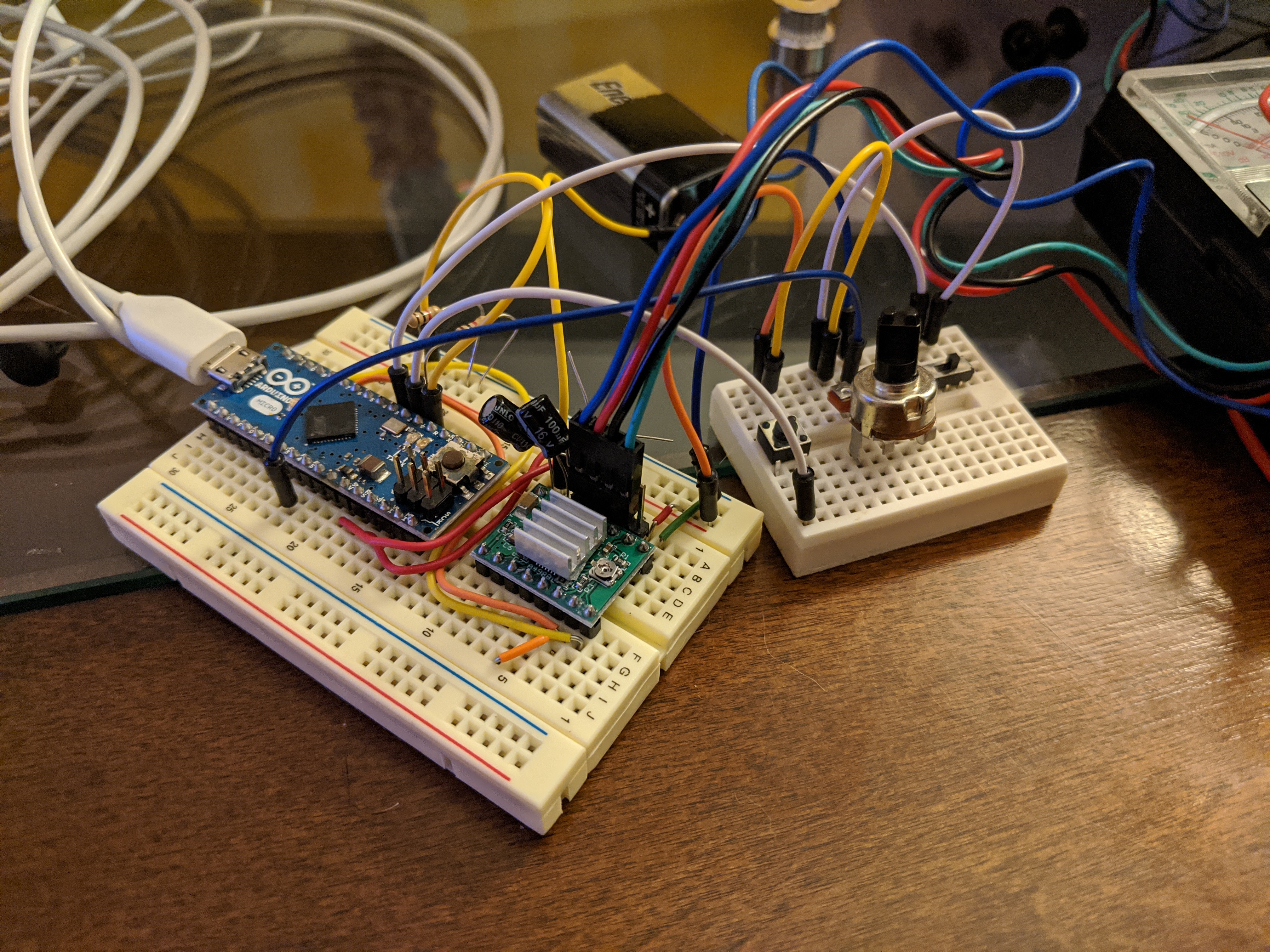
The stepper motor driver does most of the work of this circuit. We just have to wire it up so that everything has power, and the microcontroller can communicate with the driver. Both the Arduino and the motor will be powered by a 9V battery. The Arduino has on on-board voltage regulator, so it will convert this to 5 volts and we can use this as our logic power bus and the power supply for our motor driver. First, I connected the Arduino and stepper motor driver as follows:
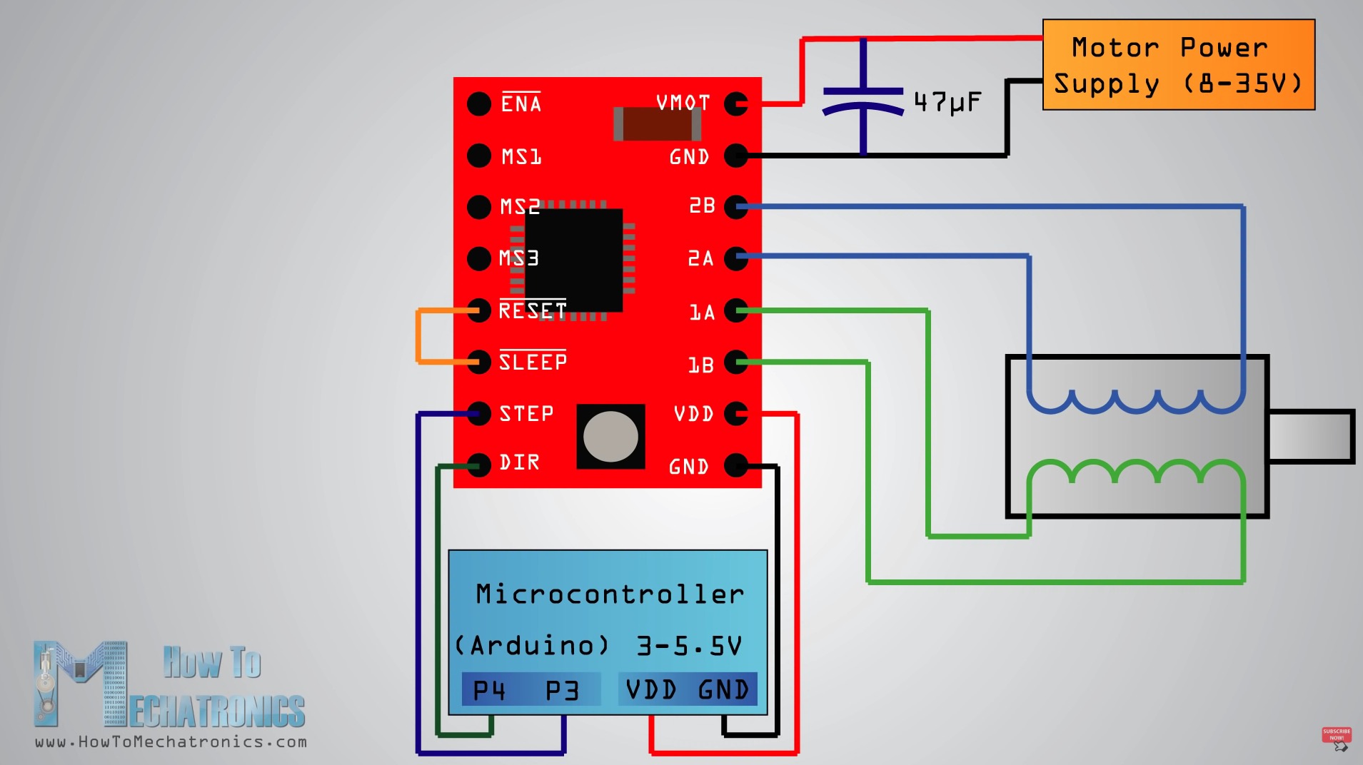
Source: How To Mechatronics
The motor driver gets two connections from the micro controller: one for the direction bit, and another for the bit that commands a single step. The pinout of this stepper motor driver was different than how my stepper motor was configured so I had to swap two wires in the 4-wire connection to the stepper motor (see "How do I connect my stepper motor to the A4988 stepper motor driver carrier?" here and notice the differences in motor coil polarity from the datasheet)
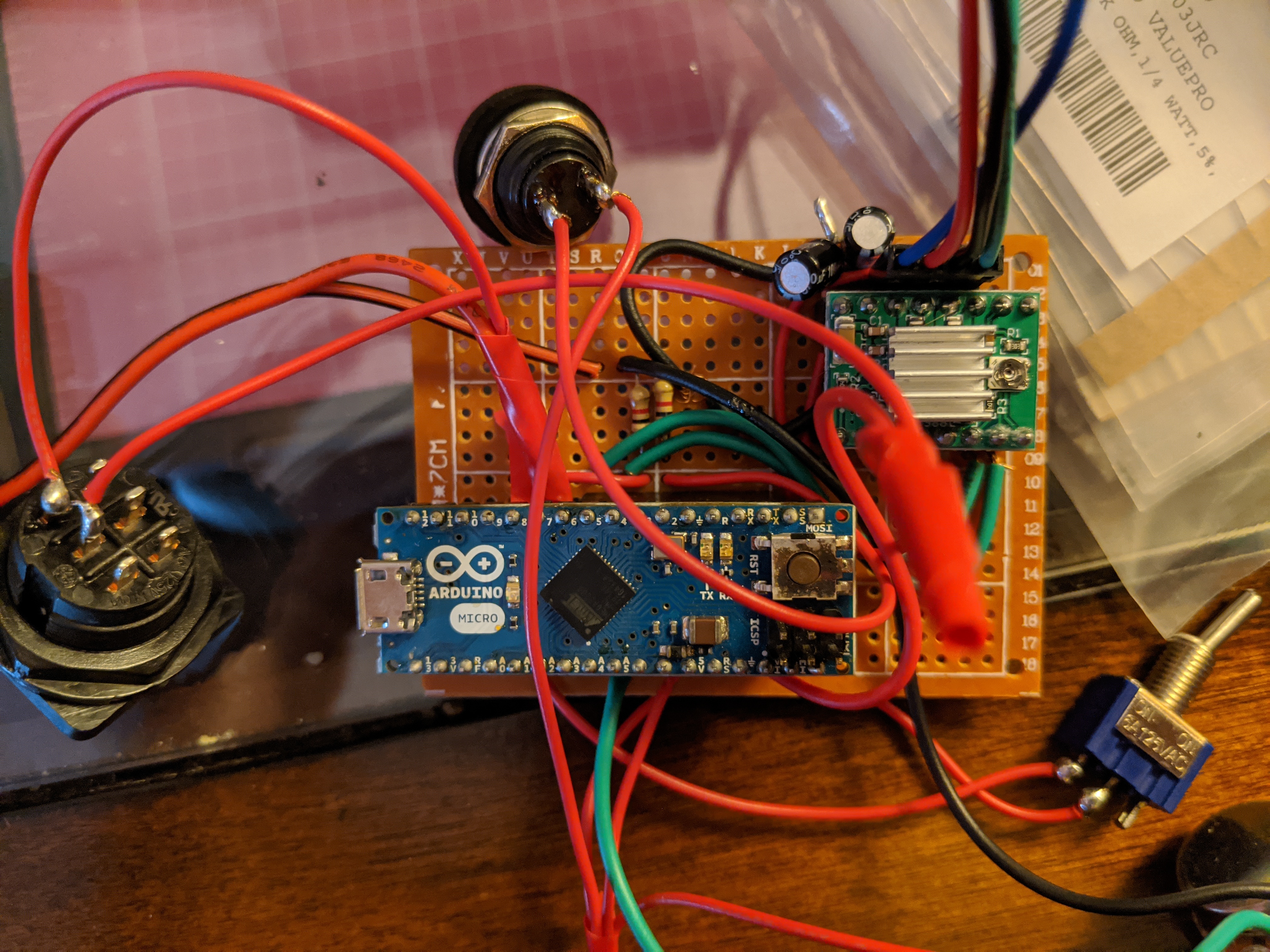
Next, we just have to connect our I/O. I used one button for start/stop, a potentiometer for the speed control, and a switch for fast/slow mode toggle. The button and switch can be hooked up from the 5V bus to any of the Arduino's digital inputs. Add a pull-down resistor so these voltages are not hanging when the switches are disconnected. The potentiometer is just an analog input. Connect one terminal to 5V, the other to ground, and the middle one goes to the Arduino's analog input. Lastly, I just added a master power switch for the 9V battery, and the electronics are done!
Code
I again loosely based my code on Max Maker's. I will briefly explain what each method does. The first is pretty self-explanitory—it moves the stepper motor. The 500 microsecond delay is as-specified in the driver datasheet.
void MoveStepper() {
          digitalWrite(stepPin, HIGH);
          delayMicroseconds(500);
          digitalWrite(stepPin, LOW);
          delayMicroseconds(500);
          Serial.print("step");
          StepsTaken++;
        }
The next method is somewhat of a work-around. For the start/stop button, I didn't have any latching push buttons, so I used a state machine to make the momentary input latch until pressed again.
bool latchStart() {
  if (StepsTaken >= Steps){ //reinitialize if end of track
    if (dir) {
      digitalWrite(dirPin, LOW);
    } else {
      digitalWrite(dirPin, HIGH);
    }
    dir = !dir;
    startState = 0;
    StepsTaken = 0;
  }
  if (startState ==0) { //initial OFF
    if (s2 == HIGH) { startState = 1;}
    return LOW;
  }
  else if (startState == 1) { //start ON
    if (s2 == LOW) { startState = 2;}
    return HIGH;
  }
  else if (startState == 2) { //latch ON
    if (s2 == HIGH) { startState = 3;}
    return HIGH;
  }
  else if (startState == 3) { //start OFF
    if (s2 == LOW) { startState = 4;}
    return LOW;
  }
  else if (startState == 4) { //latch OFF
    if (s2 == HIGH) { startState = 1;}
    return LOW;
  }
}
Next, the setTravelTime method reads the status of the analog potentiometer and the fast/slow mode toggle and sets the amount of time the slider will take to complete a full shot. The values are chose for the are
| Speed | Fast Mode | Slow Mode |
|---|---|---|
| 1 | 10s | 1h |
| 2 | 20s | 1.5h |
| 3 | 30s | 2h |
| 4 | 60s | 3h |
| 5 | 2min | 4h |
| 6 | 5mis | 6h |
| 7 | 20min | 8h |
| 8 | 30min | 10h |
| 9 | 40min | 12h |
| 10 | 50min | 14h |
The full code is available here. The rest of it is just setting up the I/O and looping through each method.
Conclision
Finally, here's a video of the slider in action and some sample footage I've taken with it.